The oscilloscope project was implemented to demonstrate the principles of coding a triggered sweep digital oscilloscope. No external controls or settings are provided. The cost of the project is minimal.
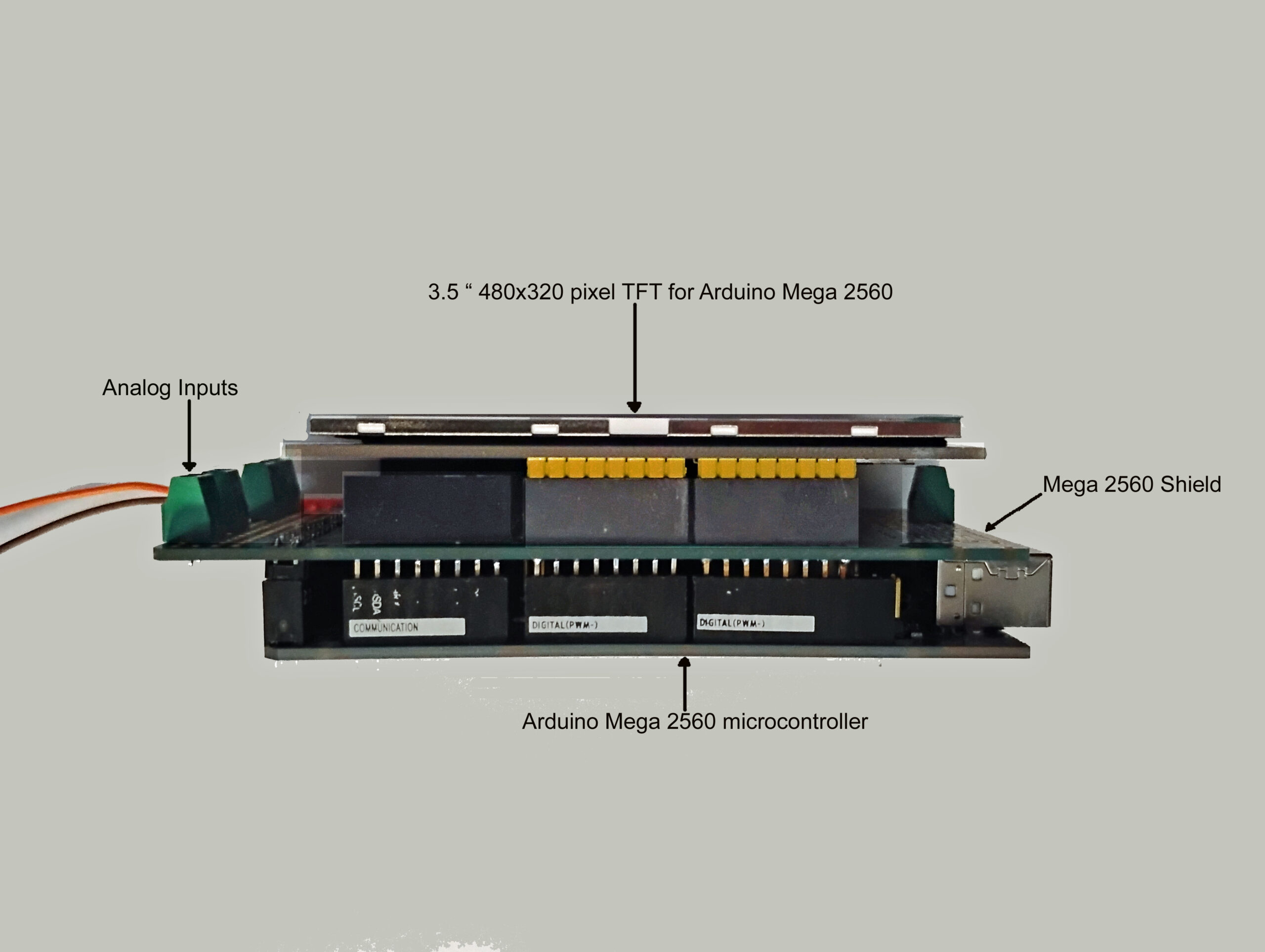
The image below shows a view of the hardware used to create the oscilloscope.
The microcontroller consists of the Arduino Mega 2560, a Mega 2560 shield and the 3.5 inch 480×320 pixel Mega 2560 TFT LCD. The TFTLCD is plugged into the shield, and the shield plugged into the Mega 2560 microcontroller. This arrangement allows wiring and terminals to be connected to the Mega 2560 via the shield.
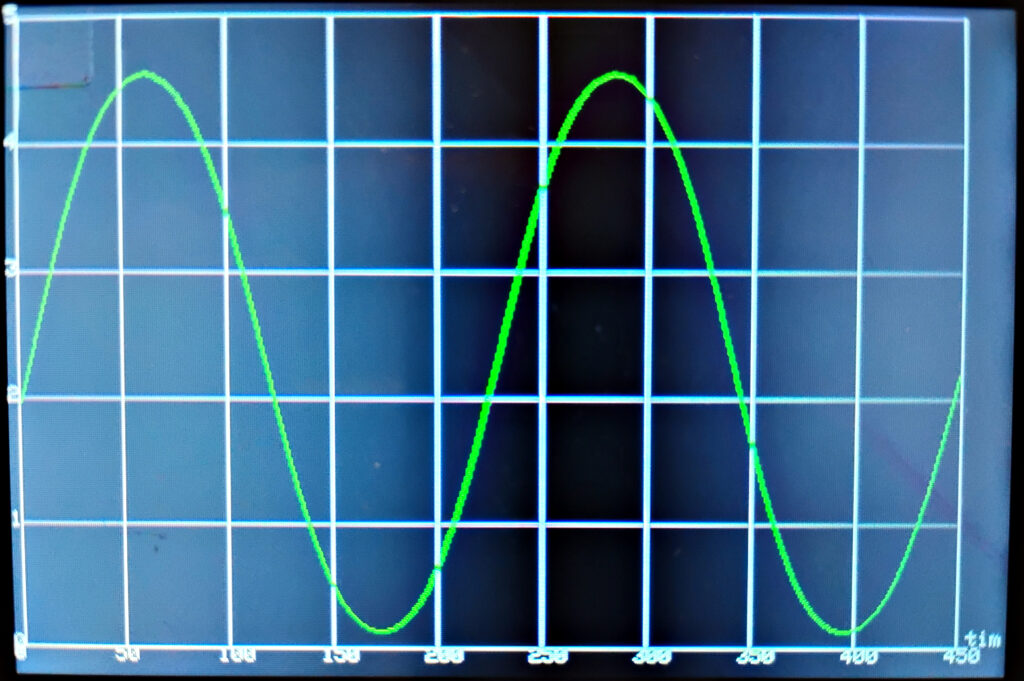
The image below is the photo of the TFTLCD screen being fed by a 4.4 Hz sine wave. The sine wave has a DC component. The peak value is approximately 4.5 volts. The oscilloscope can be triggered or free running depending on the code statement that is enabled.
The C/C++ code has been implemented in the Arduino IDE Environment.