The Spectrum Analyzer project was implemented to demonstrate the principles of coding a Spectrum Analyzer. No external controls or settings are provided. The cost of the project is minimal.
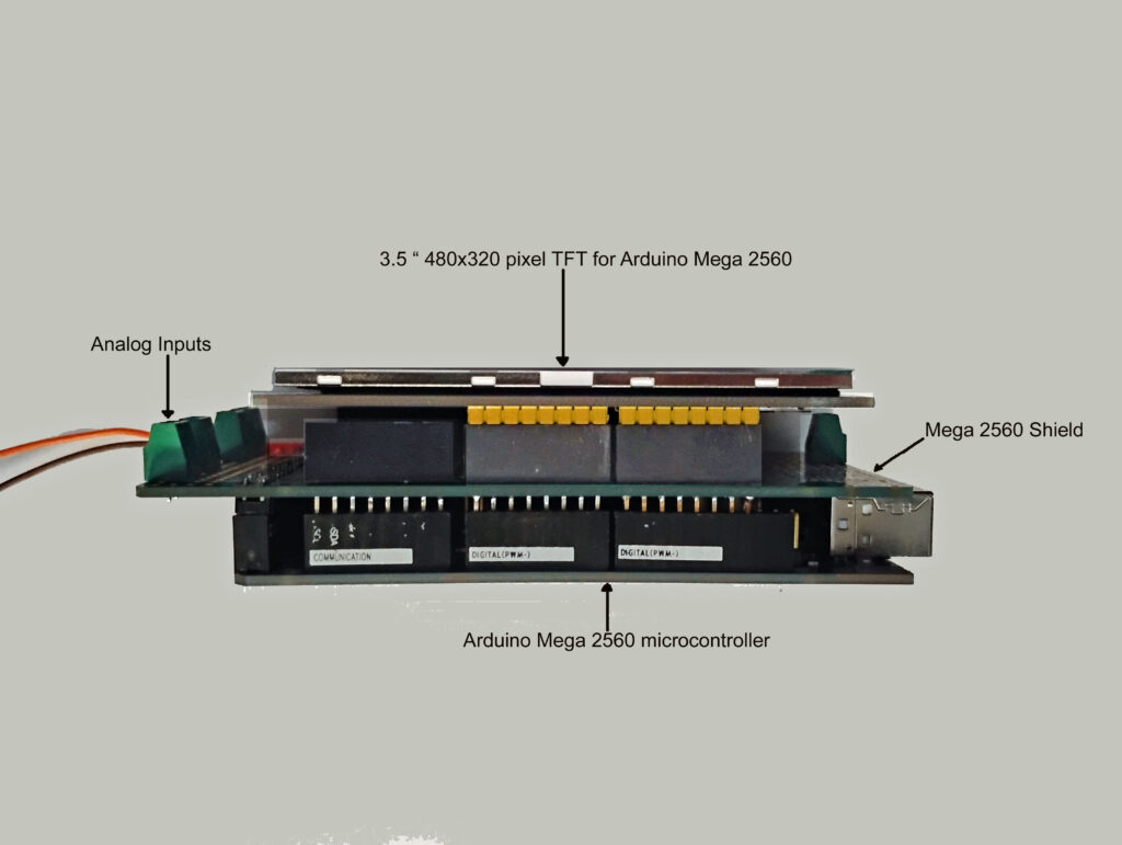
The image below shows a view of the hardware used to create the Spectrum Analyzer It is identical to the of the Oscilloscope Project shown under Projects on this web site..
The microcontroller consists of the Arduino Mega 2560, a Mega 2560 shield and the 3.5 inch 480×320 pixel Mega 2560 TFT LCD. The TFTLCD is plugged into the shield, and the shield plugged into the Mega 2560 microcontroller. This arrangement allows wiring and terminals to be connected to the Mega 2560 via the shield.
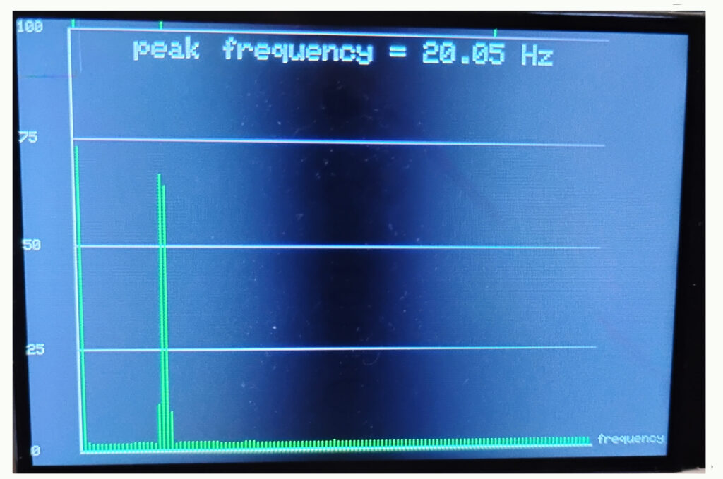
Pure Sine Wave of 20.05 Hz
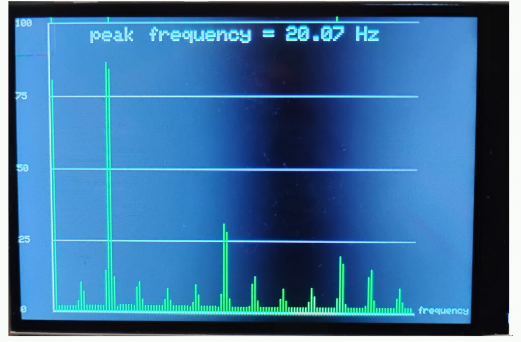
Square Wave of frequency 20.07 Hz. Note odd harmonics at 60Hz and 100Hz

Triangle Wave with small amplitude harmonics
The C/C++ code for the project was implemented using the Arduino IDE environment, and the library for the Fast Fourier Transform included is arduinoFFT.